:::: MENU ::::
Showing posts with label process. Show all posts

Monday, 7 December 2015


How It’s Made
Whether you call it a scale or a ruler, you’ve almost definitely used one at some point in your life. However, you might not have thought about how one could be modeled in SOLIDWORKS. Today we’re going to look at one of many ways to model a ruler. Our primary focus will be on making a ruler that can scale very fluidly from a 6-inch rule, to a 7.5-inch rule, to a 12-inch rule with little to no modification to our initial features. This is now easier than ever in 2015 with the capability to create linear patterns up to a reference. So let’s take a look at how I modeled a ruler in SOLIDWORKS 2015.

Modeling a Ruler
In this case, I started with the body of our ruler. I started with a sketch outlining the profile of the ruler.
Initial Sketch
After creating my sketch, I then extruded in two directions. I extruded in one direction at the desired ruler length, and in the other direction by 1/16″ to create some spacing before the first line.
Initial Boss Extruded
In order to keep the trend going, I then created an extrusion on the end to add 1/16″ after the last line. At this point, it’s time to start etching lines. We’ll create our first line centered 1/16″ from the starting edge. We’ll then cut this edge into the face using a simple blind boss extrude.
First Mark Cut Sketch
In order to create a scalable ruler, we are going to use linear patterns [Insert >> Pattern Mirror >> Linear Pattern], and we’d like to have different length lines for different segments. (ie. 1/6″, 1/8″, 1/4″, 1/2″, 1″) Because of this, we’ll start off by etching each line separately, and we’ll create separate patterns for each line.
After etching our lines like we did above, we’ll end up with something like this:
Ruler Marks Cut - Pre-Pattern
Because we’d like to make the ruler scalable, it’s best that these lines each have their own pattern. This allows for the lines to be patterned individually. My tree contained seven separate features for this as listed below. (The 1mm marks were very system intensive, so I cut three at a time to reduce the work the pattern must do.)
Cuts for Marks - Design Tree
Once we’ve created our cuts, it comes time to pattern them. We can start by patterning our one-inch mark. I’ll create the pattern using a linear pattern feature. We’ll select the feature to pattern, as well as a linear edge to define the direction. For this I selected a long edge on the ruler.
This is the key moment for making this ruler scalable. I’m going to select the option “Up to Reference”. This allows me to select an endpoint for the pattern, and to also define an offset.
First Pattern Property Manager
For my reference point, I will select an endpoint on the ruler, and I will offset it just shy of 1/16″ from the end. This ensures that I have space after the last etched line. Lastly, we’ll define the spacing of this at one inch.
First Pattern Graphics Area
I can then follow this same process to create my other patterns, filling the gaps. I did my best when creating this to prevent overlapping cuts. This will reduce the workload and rebuild time overall. I set the spacing as follows:
  • 1/16″ lines – Spaced 1/8″
  • 1/8″ lines – Spaced 1/4″
  • 1/4″ lines – Spaced 1/2″
  • 1/2″ lines – Spaced 1″
  • 10mm lines – Spaced 10mm
  • 1mm lines X 3 – Spaced 3mm (Unavoidable overlap)
Pattern Features Design Tree
After creating these patterns you will end up with something like this:
Ruler - All Lines Cut
Lastly, With our patterns configured as Up to Reference, we can freely scale the ruler and watch it update. With Instant3D enabled, we can double-click the ruler and change our dimension, and the ruler will adjust accordingly.
Ruler Scaling
Download
With that, you should be ready to rule the world of scale making. 

As always, Happy Modeling!

Monday, 16 November 2015


SOLIDWORKS Simulation (Professional and Premium package) allow us to find stress distribution on the weld connection as well as the appropriate weld size. However, calculated stress appears as a result of force applied to the welded elements, not as a result of thermal distortion which is often more important from engineering point of view.
In the following article you will find out how to estimate weld distortion using SOLIDWORKS Simulation.

Our case study consists of two metal sheets which will be welded together – we want to find out what is the distortion and stress distribution resulting from the thermal load (pic. 1). The length of weld connection is 100 [mm] and the welding speed is 0.3 [m/min] that gives us 20 seconds of welding time.
1
pic. 1  Case study – Two metal sheets which will be welded together

The first thing we have to do is to model 3D geometry of weld connection (pic. 2). Then we should split our weld model into smaller pieces adequately to the welding time – 20 seconds = 20 pieces
(pic. 3).
2
pic.2  3D model of weld connection 

3
pic.3  Weld connection after splitting


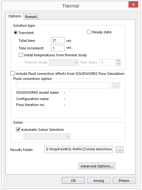
The next step is to define new thermal study. In the study properties we change Solution type to transient and the total study time to 21 seconds (pic. 4).
Now materials should be defined both for metal sheets and weld.

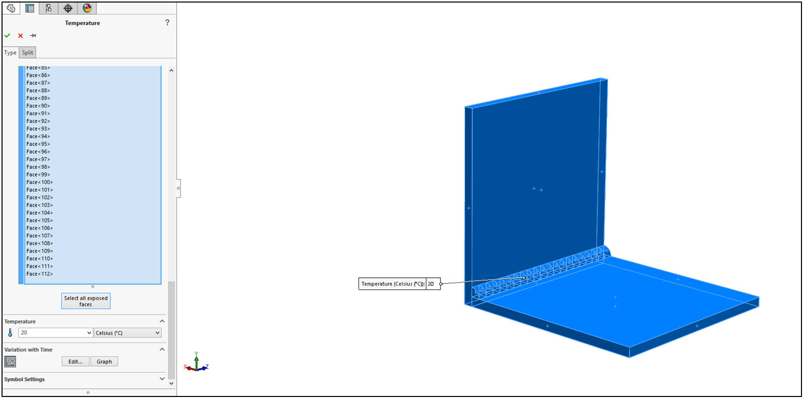
Two kind of thermal loads will be added to the study. Firstly, temperature load – we pick initial temperature and then select all exposed faces option and set the temperature to 20 [°C] (pic. 5).
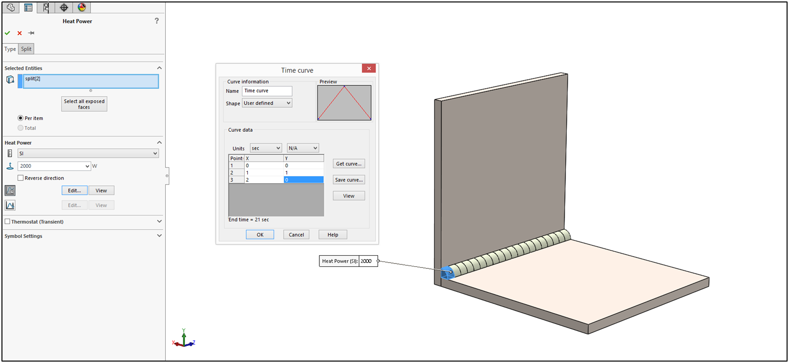
The second thermal load will be Heat power with the value of 2000 [W]. In that case we will use time curve and set it as follows – for x=0 (second 0) y=0 (no thermal load) for x=1 (second 1) y=1 (thermal load 2000 [W]) for x=2 (second 2) y=0 (no thermal load). This operation should be repeated for all the pieces of weld with proper timing (pic. 6, pic. 7).

4
pic.4 Properties of Thermal study

5 pic.5 Initial temperature definition

6pic.6 Definition of thermal loads on the first piece of weld connection

7  pic.7 Definition of thermal loads on the second piece of weld connection

Now we can run the study which results are presented below as animation.

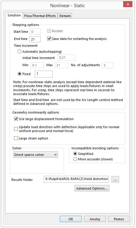
In the last step we will create nonlinear study (available only for Premium Simulation). In the study, properties in Solution tab End of stepping time should be set to 21 seconds with fixed Time increment to 1 (pic. 8). In the Flow/Thermal Effects tab Temperatures from thermal study option should be picked up (pic. 9). We add global contact – bonded and define fixed geometry on the bottom surface of bottom plate and run the study.

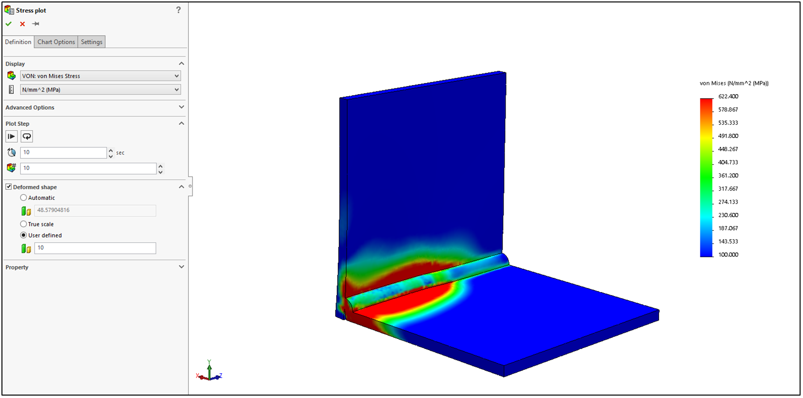
As a result we can analyze Stress distribution (pic. 10a) and Displacement plot (pic. 10b) for chosen second of the analysis or for all iterations at once (pic. 11a – stress, pic. 11b displacement). The results are also represented as animation below (stress and displacement respectively with the deformation scale of 10).
8
pic.8 Properties of Nonlinear study (Solution)
9
pic.9 Properties of Nonlinear study (Flow/Thermal Effects)

10pic.10a Stress plot in 10th second

10apic.10b Displacement plot (distortion) in 13th second

11pic.11a Stress plot for whole study

11apic.11b Displacement plot (distortion) for whole study


If you want to check up study definition on yourself you can download it from DROPBOX from link below

Wednesday, 4 November 2015


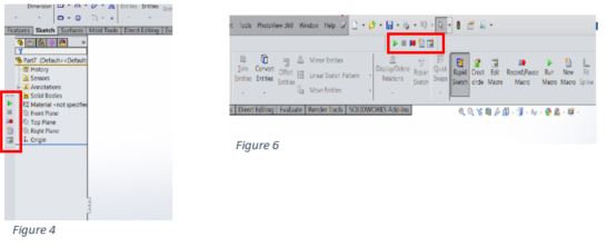
Step 1: Create a short cut to the Macro tool bar 1.1  
To do this, use either the “S” key to use the search command or head to the top right hand corner (Figure 1) and type “Macro” in the search bar.

1.2 Click on the macro option shown in Figure 2.This will bring up a small window with the macro tools shown in figure 3.

1.3 Drag and drop the window onto any side of the screen and it will attach itself to that position. (It will remain there even after closing and opening SOLIDWORKS.)
         
Step 2: Recording, saving and playing a macro

Hit the record button to start. Once the record button is hit the first time, it will grey out the play button, as shown in figure 7. This can be used to monitor if you’re recording or not.
Pausing a macro doesn’t bring back the play button but does put emphasis on the play/pause button, as shown in figure 8.


One everything is recorded, click the stop button which will prompt you to save the macro. This macro can then be opened, edited and played with the editing button**. For further information please watch:

https://www.solidsolutions.co.uk/solidworks/Tutorial-Videos/Automate-Simple-Tasks-with-the-SOLIDWORKS-Macro.aspx

Thursday, 22 October 2015

Almost every engineering student earning a bachelor’s degree will participate in a capstone design project. This project most often involves the entire engineering process, taking a design from concept to completion. This will seem like a daunting task to students, but luckily we have SOLIDWORKS to help us every step of the way. This tech tip will focus on using SOLIDWORKS to enhance that very last, and most dreaded, stage of the capstone project, the final presentation!

Visual aids are an essential part of any presentation, especially when you are conveying a design. Taking screenshots of your SOLIDWORKS models will get the point across to your audience, but they often look bland and fail to convey what the finished product will look like. Luckily, there is a powerful add-on to SOLIDWORKS, PhotoView 360, that allows you to quickly produce photorealistic renderings of your design that are sure to impress your audience. The first step is to enable the PhotoView 360 add-in in SOLIDWORKS.
PhotoView 360 SOLIDWORKS Add-In
To demonstrate how to start a photorealistic render from scratch, I’ll use the toggle clamp assembly that I made from in my previous tech tip, Creating a SOLIDWORKS Assembly from a McMaster-Carr 3D CAD File.
Toggle Clamp Assembly
As you can see in the above picture, all of the components in the assembly have their default, grey, SOLIDWORKS appearance. In order to produce a photorealistic image, you first need to apply appearances to the components. This is easy and quick to do, but you’ll need to add appearances in a few different ways to get the best result. I will show you how to add appearances to the individual components as well as to specific faces of the handle component to represent the overmolded plastic. For the purposes of this tech tip, I will only show how to add appearances, not materials.

First, I will apply Polished Steel appearance to the Base component. Launch the Appearances Property Manager by first clicking the double chevron to expand the visibility options (step 1), then click on the appearance icon corresponding to the Base component (step 2), then click “Appearance” from the menu (step 3).
Apply Polished Steel
Once the Appearances Property Manager opens, select “Apply at part document level” (step 1). We will be changing the appearance of the entire Base component, so the first option, “Select Part”, should be enabled with the Base component selected (step 2).
Apply At Part Document Level
Next, expand the “Appearances, Scenes, and Decals” tab on the right side of the screen. We want to apply a Polished Steel appearance to the Base Component. Do this by first clicking on the “Steel” subfolder found within the “Metal” folder (step 1). Then click the “Polished Steel” appearance lower on the tab (step 2). Click the green checkmark on the Appearances Property Manager to accept the applied appearance.
Polished Steel
With RealView Graphics enabled, the newly applied “Polished Steel” appearance can be seen on the Base component.
RealView Graphics Enabled
The next thing we want to do is apply the same “Polished Steel” appearance to the rest of the assembly components that require it. This can be easily done by right clicking on a component in the feature tree and selecting “Copy Appearance” (see below). This will then allow you to paste the appearance to any other component you choose and guarantees that you are using the same appearance throughout.
Copy Appearance
With the Base component’s “Polished Steel” appearance copied, group select the other components in the feature tree that you want to past the appearance to. Do this by right clicking on one of the highlighted components and click “Paste Appearance”.
Paste Appearance
The image below clearly shows the new appearance in contrast to the default, grey, SOLIDWORKS appearance.
New Appearance in Contrast with the Default Grey.
The “Handle” component requires a bit more work to get the appearances applied properly. In reality we know that the handle is made from polished steel with a rubber overmolded tip. The difficulty here is that the overmolded portion of the Handle is not a separate component. This means that individual faces of the overmolded portion need to be selected to apply a rubber appearance.

Selecting faces independently can be a lot of work, but there are a few shortcuts that you can take to do this as quickly as possible. The first trick is to determine which appearance covers the majority of the component and apply that appearance to the entire component. In the case of the Handle, there are more faces on the component that require the Polished Steel appearance than a Rubber appearance, so I applied the Polished Steel appearance to the entire component. This method works well because appearances that are applied to specific faces of the component will override the appearance assigned on the component level. To make these face selections easier, I’ve isolated the component from the assembly.
Isolated Component from the Assembly
After assigning the Polished Steel appearance to the Handle component, edit the appearance of the component again and enable the option “Select Faces”. This will allow individual faces to be selected. If the component name appears in the blue box as seen below, right-click the box and select “Clear Selections”.
Select Faces - Clear Selections
Next we need to select the rubber appearance that we want to apply. Do this by selecting a rubber appearance from the subfolder “Rubber” within the folder “Plastics” then click the “Rubber” appearance just as we did with the Polished Steel (step 1). The default color for the selected rubber is black but I want to use a red rubber. This is easily changed after selecting the appearance in step 1 by then selecting a red appearance from the color palate (step 2). This will only change the color of the rubber and will retain the textured appearance.
Select the Rubber Option Under Plastics Category; Change Rubber Color
With our custom Rubber appearance selected, now we can use our next trick. The next step is to click the faces that we want to apply the appearance to. To speed this process up, you can often take advantage of tangency between faces. By right-clicking on a face and clicking “Select Tangency” (see below), SOLIDWORKS will apply the appearance to any face that is tangent to the one you selected. I was able to apply this appearance to all but one of the faces using the “Select Tangency” option only 3 times. Any remaining faces can be easily selected independently.
Select Tangency
With all of the faces selected, just accept the applied appearances by clicking the green checkmark in the Appearances Property Manager.
The last component to be assigned an appearance is the rubber tip of the spindle. This is a separate component that can be easily assigned an appearance. We want the same red rubber appearance we applied to the handle so all we have to do is copy and paste the appearance as we did before.

With all of our appearances in place, we are ready to set up the render with PhotoView 360. My personal favorite for a simple, crisp, rendering is using the “Plain White” environment. The Plain White environment provides bright lights and minimizes any background noise from the image. Assign the Plain White appearance as seen below.
Plain White Environment Provides Bight Lights and Minimizes Any Background Noise
Now we are ready start using the PhotoView 360 tool. Access the PhotoView 360 options by navigating to the “Render Tools” tab. With the assembly positioned as you want it, click the “Preview Window” option to get a rough preview of the final render.
Render Tools Tab - Preview Window
The Preview Window will open and show you what the final render will look like with the currently applied settings. I think that the rendering looks a bit dark, which is taking away from the realism. Not to worry though because we can easily change that.
Rendering Darker Than Desired
The easiest way to improve this rendering is to use the “Environment Rotation” option located with the Scene Property Manager. Do this by clicking the “Advanced” tab and manually adjusting the Environment Rotation angle.
Environment Rotation in Scene Property Manager
Once we are happy with the render in the Preview Window, simply click “Final Render” to start the rendering. The time this takes will depend on the quality setting that were set in the Render Options. Mine were set to “Good” and took less than a minute to finish.
Final Render
It takes a few passes for the image to completely render. The last pass will look as it does below. After the render has completed, click “Save Image” and save it as you would any file in Windows.
Save Image
And here’s the final result, a crisp and simple representation of your design! I think we can all agree this is a lot better than a simple screenshot. You can use this same process for exploded and cross-section views of your model to really blow your audience away. Now you are fully equipped for your capstone presentation!

Final Result from SOLIDWORKS and PhotoView 360