:::: MENU ::::
Showing posts with label parts. Show all posts

Wednesday, 30 March 2016


Not all weldments are created equally. The standard library is a good starting point, however some profiles may not be properly dimensioned and some profiles that you need might not exist in the library. This tutorial will show you how to create your own custom profile and insert it into the SOLIDWORKS Library.

Suppose you need a weldment in the shape of a hexagon. Your first step is to sketch the profile.
001 - Pic 1

Please bare in mind that the origin will be the default point of extrusion for the weldment. Once you are satisfied with your sketch, select the sketch from the feature manager design tree, go to File > Save As.  Under “Save as type” select “Lib Feat Part”, give it a file name and save
001 - Pic 2

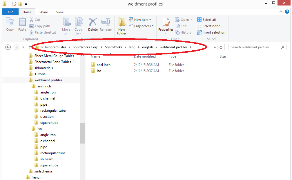
The next step is to find your weldment profile library. This can be done by going to Tools > Options. Under the System Options Tab, select “File Locations”. Under “Show folders for”, scroll down to “Weldment Profiles” and note the folder location as shown. Place a copy of the custom weldment profile into the Weldment Profiles location.
001 - Pic 3

**Important** Maintain the file structure or create a new one since SOLIDWORKS uses these file structures to designate their drop down boxes. For example a standard profile library would look as follows:
…\weldment profiles\iso\angle\ [Weldment profile file]
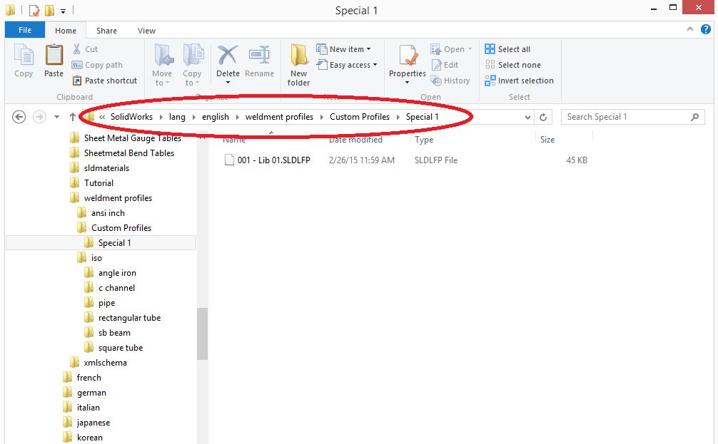
You may insert your profile under the same file structure, in this case we have created.
001 - Pic 4

…\weldment profiles\Custom Profiles\Special 1\ [Weldment profile file]
Once you have placed your custom weldment profile in place, you will be able to use it like any other weldment profile.
001 - Pic 5
 

Monday, 19 October 2015


The PropertyManager for the Convert to Sheet Metal command includes the options for Rip Edges Found (Read-Only) and Rip Sketches.  Sometimes it may not be clear what or if anything needs to be selected in these sections.  Often, there is nothing to select; these options are to be used if needed.
A rip in sheet metal is inserted if required by design and manufacturing.  The slit can go along an existing edge or a sketch line. The following examples show three simplified scenarios of the SOLIDWORKS Sheet Metal Rip Options:

Example #1: Rip not required

SOLIDWORKS Sheet Metal Rip Option
Rip not Required

Example #2: Rip selection is automatically populated after selecting first three edges

Rip selection is automatically populated
Rip Edge Automatically Selected

Example #3: Rip is based off a sketch that has been added by a designer

Rip is based off a sketch

Rip Along Sketch
Rip Along Sketch

Wednesday, 14 October 2015


When you create a sheet metal part and unsuppress the flat-pattern feature, you may discover that the flattened result is not what you expected. An example of unexpected flat pattern results is described in this tech tip. A simple sheet metal part which includes an edge flange is depicted in Fig. 1:
Example Sheet Metal Part
Fig. 1: Example Sheet Metal Part
Unsuppressing the flat-pattern feature will be result in the following figure. It seems that the flatten sheet metal is ripped off at the gap location between the two edges that define the Edge Flange feature.
Flattened Sheet Metal with Corner Treatment
Fig. 2: Flattened Sheet Metal with Corner Treatment

Corner Treatment Effect on Flatten Sheet Metal

Users should be aware that when a sheet metal is flattened, Corner Treatments are automatically applied to flattened sheet metal. In some cases similar to the example shown here, the designer may not want to have such a long gap inside their flattened sheet metal. To resolve this issue you can simply clear the Corner Treatment option in the flat-pattern feature:
Corner Treatment disabled
Fig. 3: Corner Treatment disabled
As a result, the gap between edge flanges does not penetrate into the flattened sheet metal state (see figure below)
Flatten Sheet Metal without Corner Treatment
Fig. 4: Flatten Sheet Metal without Corner Treatment

Friday, 9 October 2015


If you use a material from the SOLIDWORKS database, you are limited in how you can change the material properties. However, SOLIDWORKS User-Defined Materials allow you to apply custom material properties. Various material model types are accessible in SOLIDWORKS custom material such as Linear Elastic Isotropic, Linear Elastic Orthotropic, Nonlinear Elastic, Plasticity (von Mises / Tresca / Drucker Prager), Hyperelastic (Mooney Rivlin / Ogden / Blatz Ko), Viscoelastic, Nitinol and etc.

How to define a new material

As an example, the step by step procedure to define a new Linear Elastic Orthotropic material is shown below:

1) Right-click on any SOLIDWORKS database material and select Copy from the shortcut menu.
Copy a Material
Copy a Material
 
2) Right-click on Custom Material folder/category, then select New Category
New Material Category
 
3) Rename it. In this case, it is renamed as “New Linear Elastic Orthotropic Material”
Rename Material Category
 
4) Right-click on newly added material category and click Paste.
Paste material into new Material Category
 
5) In the Properties tab, under drop down list of Model Type, select “Linear Elastic Orthotropic”
Specify Model Type
Specify Model Type
 
6) Input values of your material properties in different directions or planes.
Add Material Properties
 
7) Furthermore, if some of the material specs are dependant on temperature, you can input them in the second tab (Tables & Curves), as follows:
Material Type Settings
 
8) Now input them manually (in order to add another row, double-click on the last point number) or you can copy and paste them from a spreadsheet data points.
Add Type Values
Add Type Values
 
9) Close the dialog when complete.
Note: if you want to download even more materials for SOLIDWORKS you can follow the steps outlined in this tech tip video.

Wednesday, 7 October 2015


Perhaps you work for a company that makes use of SOLIDWORKS custom properties. Of course you use them, they’re terrific for populating your BOM automatically and can be used for a whole host of other purposes. However, the custom properties that you use at your company are very special — one might almost say…custom.

Let’s say your company always uses four custom properties on your BOM: “Description,” “PartNo,” “Supplier,” and “Material.” However, when you download an air cylinder off of a supplier’s webpage, they do not have the same custom properties. You could populate these manually, but that would be time consuming — especially since you know that they will need all 4 properties, without typos. Did you know you can copy and paste a list of custom properties?
Copy and Paste SOLIDWORKS Custom Properties
Custom Properties dialog: select the row “1” then hold shift and select row “4”

The Copy & Paste Process

  1. First access the custom properties from File > Properties
  2. Then, select the list of custom properties from a source file by selecting the row header (where it says “1” on the left), then hold down the Shift key and select the last row (“4” in the example above). You can also use Ctrl+select to select specific properties, just as you would in Windows Explorer or the SOLIDWORKS feature tree, or many other programs.
  3. Then give it the old Ctrl+C to copy it.
  4. You can then exit the dialog window
  5. Open the new file and access the custom properties dialog and
  6. Paste the properties (Ctrl+V) into the dialog. Tada! All your custom properties now appear in the new file.
True, they are populated with the same values, some of which may need to be manually changed, but this is far, far, faster than having to recreate the properties manually.

Wednesday, 16 September 2015


Have you ever jumped right into building a model, selected a plane to begin sketching your best profile onto and then, some way into modelling felt that your models view orientations are just not quite set-up right? Perhaps you have found yourself in the drawing environment whilst pulling model views into a drawing and have noticed that certain view orientations don’t match up by name to how you thought they might?

Well here is an incredibly simple reminder of how to re-orientate your standard views in SOLIDWORKS for the many reasons that you may want to do this.

In the View Orientation drop down menu we have a variety of options for orienting your model in three dimensional space. We have 6 standard projection views and 3 standard perspective views. We can also orientate the graphics area Normal To/Perpendicular to a selection that you have made as well as the ability to tile multiple model view orientations across the display area. We can also add new custom views and use the view selector. I would like to view the front of my model now and so have went ahead and selected the Front view in the view orientation drop down. SOLDIWORKS will now rotate and zoom my model to the selected view orientation.

This orientation however is not reflective of what I would consider to be the Front of my model. I would consider the screen of my tablet model here to be the true front of it and as such would expect the Front View to match this preference.

For this reason I would like to reset the standard model views to reflect my preference and can do this by clicking the view orientation box in the heads-up view toolbar and selecting the more options arrow to the top right of the menu. I can also access this menu via the (Spacebar) keyboard shortcut or by navigating to View > Modify > Orientation.

Once inside this menu I can make changes to my view orientations by either clicking on Update standard views or Reset standard views. Resetting will allow me to revert to the original views if I make any changes that I would like to undo. Update standard views will let me make changes to my standard view orientations. I will click on Update standard views in this case.

SOLIDWORKS will then ask me to select the view that I would like to assign the current view to. But what is the “current view” that SOLIDWORKS is referring to? Simply, whatever orientation I currently have my model placed in on my screen. That orientation will be assigned to the standard view that I select in the menu. So be aware that you could orientate your model in any way, Normal To a particular area of the model or indeed completely arbitrarily if you wanted to.

I have now orientated my model to what I consider to be the bottom of the Tablet and as this is my “current view”, upon selection of the standard bottom view icon in the view orientation menu, my “current view” will be assigned to this. SOLIDWORKS will now inform me that various other views will be affected if I assign this new view orientation to my model. Happy that I am ok with this, I will select yes to proceed.

Whenever I do this, all of the standard views will be updated based upon the re-assigned bottom view. The comparison given below shows the change that this will now make to each of the standard views. I managed to divide my screen like this by selecting the Four view tile option in the view orientation menu.

The image above displays my original model orientation and the image below, the new. Pay particular attention to the name of each view orientation. ie. *Front, *Left, * Top, *Isometric.

I hope that you can find a use for this month’s very simple tech blog or that it has solved any headaches that you may have had when orientating your model in the display area. The benefit of making these changes helps you more intuitively flow between model views and extends into the drawing environment as well which can save any confusion between drawing view names and their orientation.

Tuesday, 15 September 2015


In a previous blog, “How to create a library design feature in SOLIDWORKS”, we saw how we could create library features, now we will look at how we can take those library features and incorporate the new and improved patterning tool options that were introduced within the 2015 release of SOLIDWORKS. As many users have already found the new options very useful we have tried to push the limits of the new options and have found some very useful ways in which they can be used. In this blog we will look at how we create these intelligent library features by using the new patterning tools and how we can apply these to our parts. In this blog we will use a set of simple cut outs and bodies to demonstrate intelligent library features.

CREATING THE LIBRARY FEATURE:

We do not need to do anything special to create these library features, they can be created in the same way as normal library features but just incorporating the patterning tools. The first step is to create the design required, in this case some simple cuts and bodies.

Firstly, just like smart components, we need a defining part file. This will be where we define the library feature and choose what features or bodies we will use for a library feature.
So in this scenario we will create a worktop with simple cut outs and bodies to fit into the cut outs. We have created a base worktop with a secondary worktop that sits above it with a cut out through both worktops and a container that fits into the cut out.
Library_1

Library_2

We now need to apply the patterning feature with the spacing options needed. As we have placed the container in the centre of the worktop we will be using the pattern seed feature option. We will first pattern the cut out and then the container.

 Within the patterning tool if we select our direction 1 and 2 as the same edge and choose out pattern seed feature, we specify our spacing options for each direction.
Library_3
Next we will choose the new options for Up to reference in each direction. This will allow us to use a offset edge to control how far in the pattern will be from the edge specified and this will also build intelligence into the part, as we increase the length of the worktop the pattern will increase or decrease, giving us more or less cut outs in the worktop.
Prior to SOLIDWORKS 2015 and this enchantment in particular, users would have to create a pattern and then use a function within the modify dialog box to make the intelligent update work, Increasing the workflow steps required and also the time involved in creating an intelligent model.
Library_4

Once the user has set clicked ok the intelligent pattern has been created. To test this, the user can change the overall size and see the parts start to update. In this example we have set the dimension reference or the upper worktop from the edge of the lower worktop so as we change the size of the lower worktop the upper will change automatically.
Library_5

We have repeated the previous pattern for the container but just pick the bodies to pattern instead of features to pattern to achieve the desired result.
Library_6
If we increase the size of the lower worktop from 400mm to 600mm we will see the pattern increase the cut out and containers to 5 instead of 3.
Library_7
Using these great tools has allowed us to quickly create the desired effect. Now we will go on to create the intelligent library feature.

 Just like creating any library feature, if we select the features we would like in the library feature from the feature tree we can then save the desired features as our library features from the normal save menu but picking the Lib Feat Part (.sldlfp) from the Save As Type list.
Library_8

Library_9
This will then save all the features required as a library feature file we can then use in any part. We would ideally like to put these library parts into a common folder that we can access. Once in this common folder we can set a folder location in the design library to always see these newly created library parts.

USING THE INTELLIGENT LIBRARY PARTS:

 We have set a folder location on our design library to show all the intelligent library features we have created, including the one in this blog. We have done this by using the Add File Location button on the design library in the task pane. We will now use the created library feature within a new part.
As an example we have created just a rectangular boss 800mm X 200mm in a new part file.
Library_10

We will now drag and drop our newly created library feature from our design library location
Library_11
Once out Placement Plane has been selected, we can now start setting the references required. This will be the edges used to create the upper worktop. The preview window will show what edges, faces or sketch points to pick.
Library_12
As we can see the library feature has updated and added an extra 2 containers and cut outs to the desired worktop.

 If we take the 800mm length down to 400mm the extra 4 containers reduces, this build our intelligent library feature.
Library_13
A fantastic way to automate feature and body creation as well as allowing the user a quick and easy way to develop the design as requested. Using intelligent library feature within a design could save a lot of time, effort and development of a product. This is one of the many way the new options within SOLIDWORKS 2015 can help users create some very dynamic parts.

Tuesday, 1 September 2015


Hold down your right mouse button and slowly move your mouse pointer. The ‘wheel’ that appears on your screen is the in-context mouse gesture shortcut toolbar, and each of the icons is a shortcut.
Just swipe the mouse pointer over an icon and you will instantly access that command. The gesture wheel is fully customisable, so you can have up to 8 different shortcuts, and its in-context, so you see different shortcuts if you are in sketch, part, drawings or assembly mode.
Techie_1

Techie_2
 To customise the wheel, right click on the command manager toolbar and select Customize:
Techie_3   Techie_4
 Select the Mouse Gestures tab, here you can select 4 or 8 wheel gestures.
Techie_5
Tip: A slow double click on the column title will sort already set shortcuts.
Techie_6To set a shortcut either scroll down the list or use search tool to find the command you want, then click in the relevant column and cell to set its wheel position:

Techie_7
After a bit of practice and as you start to remember the wheel positions you will become faster and more productive, you can also print the gestures list out and keep a copy by your machine (ensure that “Show only commands with mouse gestures assigned” is checked before printing):
Techie_8