:::: MENU ::::

Wednesday 30 March 2016


Not all weldments are created equally. The standard library is a good starting point, however some profiles may not be properly dimensioned and some profiles that you need might not exist in the library. This tutorial will show you how to create your own custom profile and insert it into the SOLIDWORKS Library.

Suppose you need a weldment in the shape of a hexagon. Your first step is to sketch the profile.
001 - Pic 1

Please bare in mind that the origin will be the default point of extrusion for the weldment. Once you are satisfied with your sketch, select the sketch from the feature manager design tree, go to File > Save As.  Under “Save as type” select “Lib Feat Part”, give it a file name and save
001 - Pic 2

The next step is to find your weldment profile library. This can be done by going to Tools > Options. Under the System Options Tab, select “File Locations”. Under “Show folders for”, scroll down to “Weldment Profiles” and note the folder location as shown. Place a copy of the custom weldment profile into the Weldment Profiles location.
001 - Pic 3

**Important** Maintain the file structure or create a new one since SOLIDWORKS uses these file structures to designate their drop down boxes. For example a standard profile library would look as follows:
…\weldment profiles\iso\angle\ [Weldment profile file]
You may insert your profile under the same file structure, in this case we have created.
001 - Pic 4

…\weldment profiles\Custom Profiles\Special 1\ [Weldment profile file]
Once you have placed your custom weldment profile in place, you will be able to use it like any other weldment profile.
001 - Pic 5
 

Monday 29 February 2016


Often times, in SOLIDWORKS, we will need to apply multiple mates of a similar type in an assembly. There is an option called SOLIDWORKS Multiple Mate Mode that can accomplish this. This process works with all kinds of mates, but it’s easily demonstrated here with the concentric mate. Please consider the following assembly:
I'd like to make everything concentric to the bolt
I’d like to make everything concentric to the bolt
Looking at the assembly, there is one bolt, 3 washers, 3 lock washers and 3 nuts. Using traditional mate selection methods, you would require 18 selection clicks. What if I told you it could be done in 10? Let’s check it out. If I launch the mate command from the toolbars, I take notice of the button indicated:
Multiple Mate Mode
Multiple Mate Mode
Using this button changes the interface on the side a bit. It allows me to select one as a common reference (in my example, the cylindrical face on the bolt) and then select as many other references as I like (a cylindrical face on each of the other components). Behold:
SOLIDWORKS Multiple Mate Mode
Applying a Multi Mate
This is likely enough for most people, but it you want to get really fancy, there’s a checkbox for “Create multi-mate folder” that you might notice in the above screenshot. Here is what that option does:
Multi-mate folder
Multi-mate folder

Wednesday 24 February 2016


SOLIDWORKS has had, and continues to have all kinds of functionality embedded in the most basic of windows commands – Take the “Copy” command for example.  In this example we will use simple Copy & Paste Functionality to make an exact copy of the sketch and maintain the relations applied to the original.

Copy and Paste Sketch Process

The Basic Workflow to copy the sketch is simple:
  1. Select the source Sketch
  2. Type CTRL+C as a shortcut for the “Copy” command
  3. Select the Plane that will receive the sketch
  4. Type CTRL+P as a shortcut fr the “Paste” command
Copy a Sketch and Maintain the Sketch Relations
Copy Sketch
As with most things, it turns out there is a little bit more to the story here to be a complete success. Upon pasting the sketch you may discover that the geometry appears Under-defined, which is the spot where most folks give up and turn back.
Copy Sketch Plane is different
The reason the copied sketch becomes under defined is due to the lack of relations that are controlling the location of the sketch with reference to the origin. The original sketch had a coincident relation that held the lower left corner of the sketch on the origin.
Define sketch
Under defined sketch
If you add some dimensions or relations to control the location of the sketch, or simply add a fixed relation – The sketch will then become fully defined and ready for reuse.
Fully defined sketch

Thursday 4 February 2016


Every now and then you open a file and a message comes up warning you about a file being inaccessible and whether or not you want to suppress this, at the same time this warning may give you the Don’t show again option:

Dismissed-message-solidworks

But now whenever you open an assembly and a part is missing there is no warning message to let you know, so how do we get this back?

To access your dismissed messages you will need to navigate to Tools> Options> System Options> Messages/Errors/Warnings. Once there you will have a couple of options however the area at the bottom of the window is of interest to us, this is where all the messages which have been dismissed using the “don’t show again “options will be.

Dismissed-message-solidworks-2

For instance in mine I know have the message for the unable to locate the file as I dismissed. When I now check the box next to this message it will be removed from the list, once I select OK at the bottom, and be brought back into force. So that the next time I open a file which is missing a component the warning dialog is once again clearly displayed.

Tuesday 8 December 2015


I thought I’d share with you a game changer. Something that once you see it, it will make you look at SOLIDWORKS in a completely different light and in an even more positive way. A lot of you may already be aware of 3DContentCentral and GrabCAD, but are you aware of The Foundry Community?

The Foundry community is an asset site. A place where people share materials and appearances. These aren’t just normal off the shelf appearances though. Although there are classic appearances available such as plastics and metals, there are also appearances like Elmo Fur, Dirt, Cracked Paint, rust and a green lava blob just to name a few. These new appearances are something that can take your rendering to the next level. You’ll no longer be limited to the standard appearances in SOLIDWORKS.
SOLIDWORKS Rendering PhotoView360
Step 1.
The first thing you’ll need to do once you’ve built a model is sign up to The Foundry Community. This is completely free and once you’ve signed up, you’ll have access to 1000s of different appearances.
SOLIDWORKS Rendering PhotoView360
Step 2.
The next thing you’ll want to do is simply browse for the look you’re after. Once you’ve found the one you want, simply accept the terms and conditions and press download.
When you press the download button, the zip file opens in windows explorer.
SOLIDWORKS Rendering PhotoView360
Step 3.
When the zip files opens in windows explorer simply move it out of the way and when in SOLIDWORKS taskpane click on the appearances tab.
There are various ways you can save the new appearance in the appearances folders. But for now we are simply going to create a new folder called ‘Foundry’ in the appearance library. You can name yours whatever you like or whatever you feel will be most suitable.
SOLIDWORKS Rendering PhotoView360
Right click on the appearances folder and click open folder. Next create a new folder called ‘foundry’ and drag the .lxp file from the downloaded zip file into the ‘Foundry’ folder. Refresh the folder and your new appearance will be ready to apply and use like all of the other appearances
Step 4.
Apply the new appearance onto the face/body/part. Notice the appearance appears in the graphics window as 2D. This is because surface finishes only appear when rendering occurs. You can however preview the new appearance using the preview render functionality of  PhotoView360.
SOLIDWORKS Rendering PhotoView360
Here is an example that I carried out to show you the kind of affects that you can achieve by using this new appearance library.
Photoview 360 is included in both SOLIDWORKS Professional and SOLIDWORKS Premium software packages.

Monday 7 December 2015


How It’s Made
Whether you call it a scale or a ruler, you’ve almost definitely used one at some point in your life. However, you might not have thought about how one could be modeled in SOLIDWORKS. Today we’re going to look at one of many ways to model a ruler. Our primary focus will be on making a ruler that can scale very fluidly from a 6-inch rule, to a 7.5-inch rule, to a 12-inch rule with little to no modification to our initial features. This is now easier than ever in 2015 with the capability to create linear patterns up to a reference. So let’s take a look at how I modeled a ruler in SOLIDWORKS 2015.

Modeling a Ruler
In this case, I started with the body of our ruler. I started with a sketch outlining the profile of the ruler.
Initial Sketch
After creating my sketch, I then extruded in two directions. I extruded in one direction at the desired ruler length, and in the other direction by 1/16″ to create some spacing before the first line.
Initial Boss Extruded
In order to keep the trend going, I then created an extrusion on the end to add 1/16″ after the last line. At this point, it’s time to start etching lines. We’ll create our first line centered 1/16″ from the starting edge. We’ll then cut this edge into the face using a simple blind boss extrude.
First Mark Cut Sketch
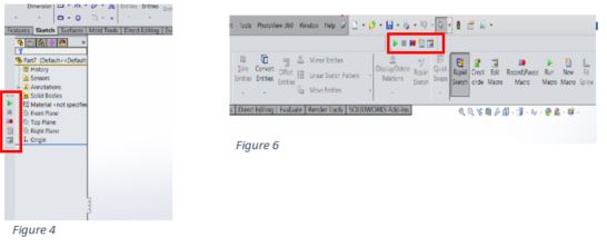
In order to create a scalable ruler, we are going to use linear patterns [Insert >> Pattern Mirror >> Linear Pattern], and we’d like to have different length lines for different segments. (ie. 1/6″, 1/8″, 1/4″, 1/2″, 1″) Because of this, we’ll start off by etching each line separately, and we’ll create separate patterns for each line.
After etching our lines like we did above, we’ll end up with something like this:
Ruler Marks Cut - Pre-Pattern
Because we’d like to make the ruler scalable, it’s best that these lines each have their own pattern. This allows for the lines to be patterned individually. My tree contained seven separate features for this as listed below. (The 1mm marks were very system intensive, so I cut three at a time to reduce the work the pattern must do.)
Cuts for Marks - Design Tree
Once we’ve created our cuts, it comes time to pattern them. We can start by patterning our one-inch mark. I’ll create the pattern using a linear pattern feature. We’ll select the feature to pattern, as well as a linear edge to define the direction. For this I selected a long edge on the ruler.
This is the key moment for making this ruler scalable. I’m going to select the option “Up to Reference”. This allows me to select an endpoint for the pattern, and to also define an offset.
First Pattern Property Manager
For my reference point, I will select an endpoint on the ruler, and I will offset it just shy of 1/16″ from the end. This ensures that I have space after the last etched line. Lastly, we’ll define the spacing of this at one inch.
First Pattern Graphics Area
I can then follow this same process to create my other patterns, filling the gaps. I did my best when creating this to prevent overlapping cuts. This will reduce the workload and rebuild time overall. I set the spacing as follows:
  • 1/16″ lines – Spaced 1/8″
  • 1/8″ lines – Spaced 1/4″
  • 1/4″ lines – Spaced 1/2″
  • 1/2″ lines – Spaced 1″
  • 10mm lines – Spaced 10mm
  • 1mm lines X 3 – Spaced 3mm (Unavoidable overlap)
Pattern Features Design Tree
After creating these patterns you will end up with something like this:
Ruler - All Lines Cut
Lastly, With our patterns configured as Up to Reference, we can freely scale the ruler and watch it update. With Instant3D enabled, we can double-click the ruler and change our dimension, and the ruler will adjust accordingly.
Ruler Scaling
Download
With that, you should be ready to rule the world of scale making. 

As always, Happy Modeling!

Wednesday 18 November 2015


From what I’ve experienced of the newest release of 2016 SOLIDWORKS features, SOLIDWORKS was focused on decreasing design time by reducing distractions in the interface. And, for an added bonus, make your mouse seem a bit lazy.

Earlier, I discussed a few Tried-and-True SOLIDWORKS Features to Help You Design Faster.
Below, you’ll see some of the 2016 additions that complement the prior quick tricks.

New 2016 SOLIDWORKS Features:

  1. Auto Resize Property Manager Selection BoxesThere are times when the smallest of things make the biggest differences – this enhancement is definitely one of them. When you have selection box in the property manager that is too small for all the selections, SOLIDWORKS will now automatically resize it for you.  And, if you don’t like the new size, change it by dragging on the little dot under the box and auto size it back with a double-click. It’s a small change, but noticeable.
  2. Foreshortened DimensionsFor some time now, you have been able to foreshorten an angular dimension in SOLIDWORKS. Now, that capability has been extended to linear dimensions.  If you have a dimension that is too long for your drawing view, SOLIDWORKS can clip it to fit the view with a right-click->Display Options->Foreshorten.
  3. Moving Confirmation CornerSometimes when you are working in a feature, your mouse cursor will change up and let you know that you can just do a right-click to accept the command; many times you have to move to the far right or far left to select the check box.  In 2016, SOLIDWORKS has completely eliminated your mouse from having to move to accept a command by first pressing the ‘D’ key and the confirmation corner will come to your mouse! Hence the lazy mouse mention from above.
  4. Tab/Shift-Tab to Hide/Show Components
    To expand on the very handy tab/shift-tab shortcut in assemblies, SOLIDWORKS uses the same keys to hide/show bodies and surfaces inside of parts. This can save tremendous amounts of time without having to click and select hide/show on each body.Keyboard-left_keys
  5. Midpoint HighlightMidpoints have been on center stage for the last few years with the new mid-point line in 2015 and now midpoints being selectable with the mouse. You have always been able to select a midpoint while sketching a new entity or with a right-click->select midpoint. Now, you can just select them. A big advantage, you can select two midpoints and make them coincident without having to pull tricks out with points, right-clicks, or some other obscure method you found.
These are just some of the very handy tidbits that SOLIDWORKS has included in 2016 to help make your design efforts more productive. For your reference, here’s a quick overview of What’s New in SOLIDWORKS 2016.

Monday 16 November 2015


SOLIDWORKS Simulation (Professional and Premium package) allow us to find stress distribution on the weld connection as well as the appropriate weld size. However, calculated stress appears as a result of force applied to the welded elements, not as a result of thermal distortion which is often more important from engineering point of view.
In the following article you will find out how to estimate weld distortion using SOLIDWORKS Simulation.

Our case study consists of two metal sheets which will be welded together – we want to find out what is the distortion and stress distribution resulting from the thermal load (pic. 1). The length of weld connection is 100 [mm] and the welding speed is 0.3 [m/min] that gives us 20 seconds of welding time.
1
pic. 1  Case study – Two metal sheets which will be welded together

The first thing we have to do is to model 3D geometry of weld connection (pic. 2). Then we should split our weld model into smaller pieces adequately to the welding time – 20 seconds = 20 pieces
(pic. 3).
2
pic.2  3D model of weld connection 

3
pic.3  Weld connection after splitting


The next step is to define new thermal study. In the study properties we change Solution type to transient and the total study time to 21 seconds (pic. 4).
Now materials should be defined both for metal sheets and weld.

Two kind of thermal loads will be added to the study. Firstly, temperature load – we pick initial temperature and then select all exposed faces option and set the temperature to 20 [°C] (pic. 5).
The second thermal load will be Heat power with the value of 2000 [W]. In that case we will use time curve and set it as follows – for x=0 (second 0) y=0 (no thermal load) for x=1 (second 1) y=1 (thermal load 2000 [W]) for x=2 (second 2) y=0 (no thermal load). This operation should be repeated for all the pieces of weld with proper timing (pic. 6, pic. 7).

4
pic.4 Properties of Thermal study

5 
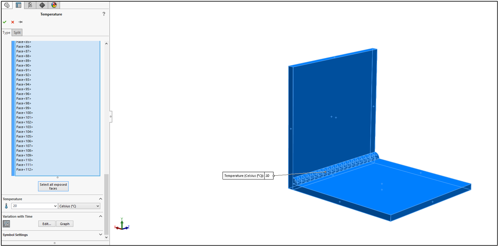
pic.5 Initial temperature definition

6
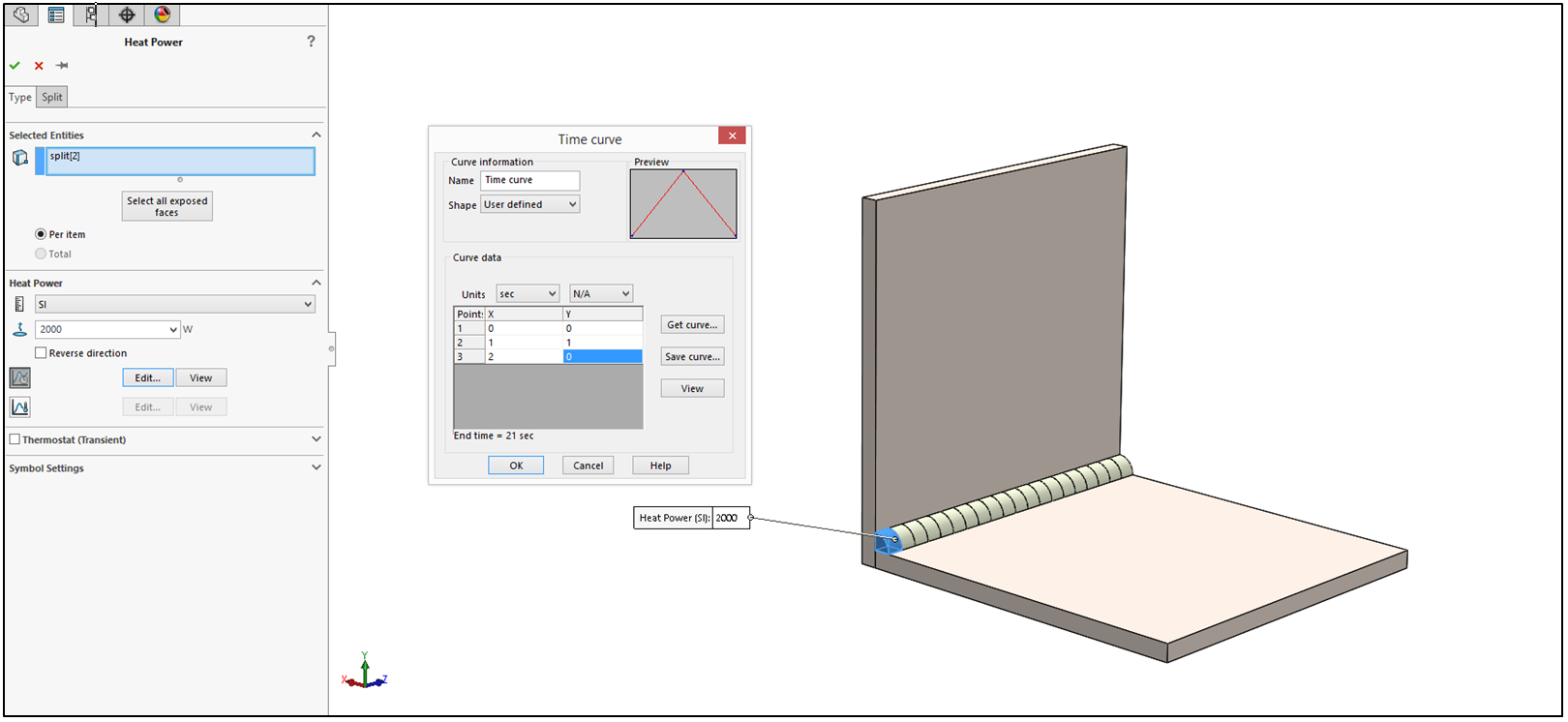
pic.6 Definition of thermal loads on the first piece of weld connection

7  pic.7 Definition of thermal loads on the second piece of weld connection

Now we can run the study which results are presented below as animation.

In the last step we will create nonlinear study (available only for Premium Simulation). In the study, properties in Solution tab End of stepping time should be set to 21 seconds with fixed Time increment to 1 (pic. 8). In the Flow/Thermal Effects tab Temperatures from thermal study option should be picked up (pic. 9). We add global contact – bonded and define fixed geometry on the bottom surface of bottom plate and run the study.

As a result we can analyze Stress distribution (pic. 10a) and Displacement plot (pic. 10b) for chosen second of the analysis or for all iterations at once (pic. 11a – stress, pic. 11b displacement). The results are also represented as animation below (stress and displacement respectively with the deformation scale of 10).
8
pic.8 Properties of Nonlinear study (Solution)
9
pic.9 Properties of Nonlinear study (Flow/Thermal Effects)

10
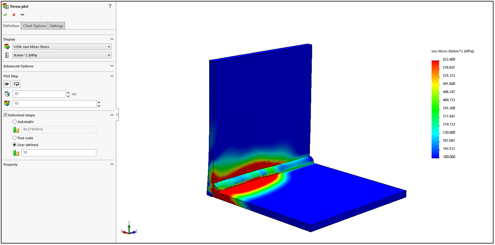
pic.10a Stress plot in 10th second

10apic.10b Displacement plot (distortion) in 13th second

11pic.11a Stress plot for whole study

11apic.11b Displacement plot (distortion) for whole study


If you want to check up study definition on yourself you can download it from DROPBOX from link below

Wednesday 4 November 2015


Step 1: Create a short cut to the Macro tool bar 1.1  
To do this, use either the “S” key to use the search command or head to the top right hand corner (Figure 1) and type “Macro” in the search bar.

1.2 Click on the macro option shown in Figure 2.This will bring up a small window with the macro tools shown in figure 3.

1.3 Drag and drop the window onto any side of the screen and it will attach itself to that position. (It will remain there even after closing and opening SOLIDWORKS.)
         
Step 2: Recording, saving and playing a macro

Hit the record button to start. Once the record button is hit the first time, it will grey out the play button, as shown in figure 7. This can be used to monitor if you’re recording or not.
Pausing a macro doesn’t bring back the play button but does put emphasis on the play/pause button, as shown in figure 8.


One everything is recorded, click the stop button which will prompt you to save the macro. This macro can then be opened, edited and played with the editing button**. For further information please watch:

https://www.solidsolutions.co.uk/solidworks/Tutorial-Videos/Automate-Simple-Tasks-with-the-SOLIDWORKS-Macro.aspx