
SOLIDWORKS Simulation (Professional and Premium package) allow us to find stress distribution on the weld connection as well as the appropriate weld size. However, calculated stress appears as a result of force applied to the welded elements, not as a result of thermal distortion which is often more important from engineering point of view.
In the following article you will find out how to estimate weld distortion using SOLIDWORKS Simulation.
Our case study consists of two metal sheets which will be welded together – we want to find out what is the distortion and stress distribution resulting from the thermal load (pic. 1). The length of weld connection is 100 [mm] and the welding speed is 0.3 [m/min] that gives us 20 seconds of welding time.

pic. 1 Case study – Two metal sheets which will be welded together
The first thing we have to do is to model 3D geometry of weld connection (pic. 2). Then we should split our weld model into smaller pieces adequately to the welding time – 20 seconds = 20 pieces
(pic. 3).

pic.2 3D model of weld connection

pic.3 Weld connection after splitting
The next step is to define new thermal study. In the study properties we change Solution type to transient and the total study time to 21 seconds (pic. 4).
Now materials should be defined both for metal sheets and weld.
Two kind of thermal loads will be added to the study. Firstly, temperature load – we pick initial temperature and then select all exposed faces option and set the temperature to 20 [°C] (pic. 5).
The second thermal load will be Heat power with the value of 2000 [W]. In that case we will use time curve and set it as follows – for x=0 (second 0) y=0 (no thermal load) for x=1 (second 1) y=1 (thermal load 2000 [W]) for x=2 (second 2) y=0 (no thermal load). This operation should be repeated for all the pieces of weld with proper timing (pic. 6, pic. 7).
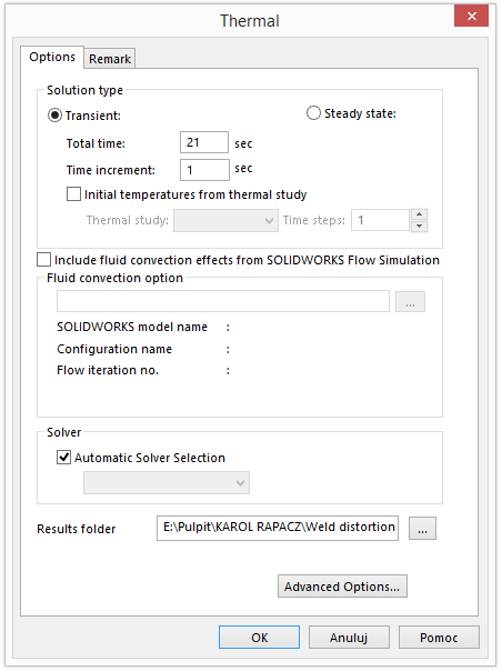
pic.4 Properties of Thermal study
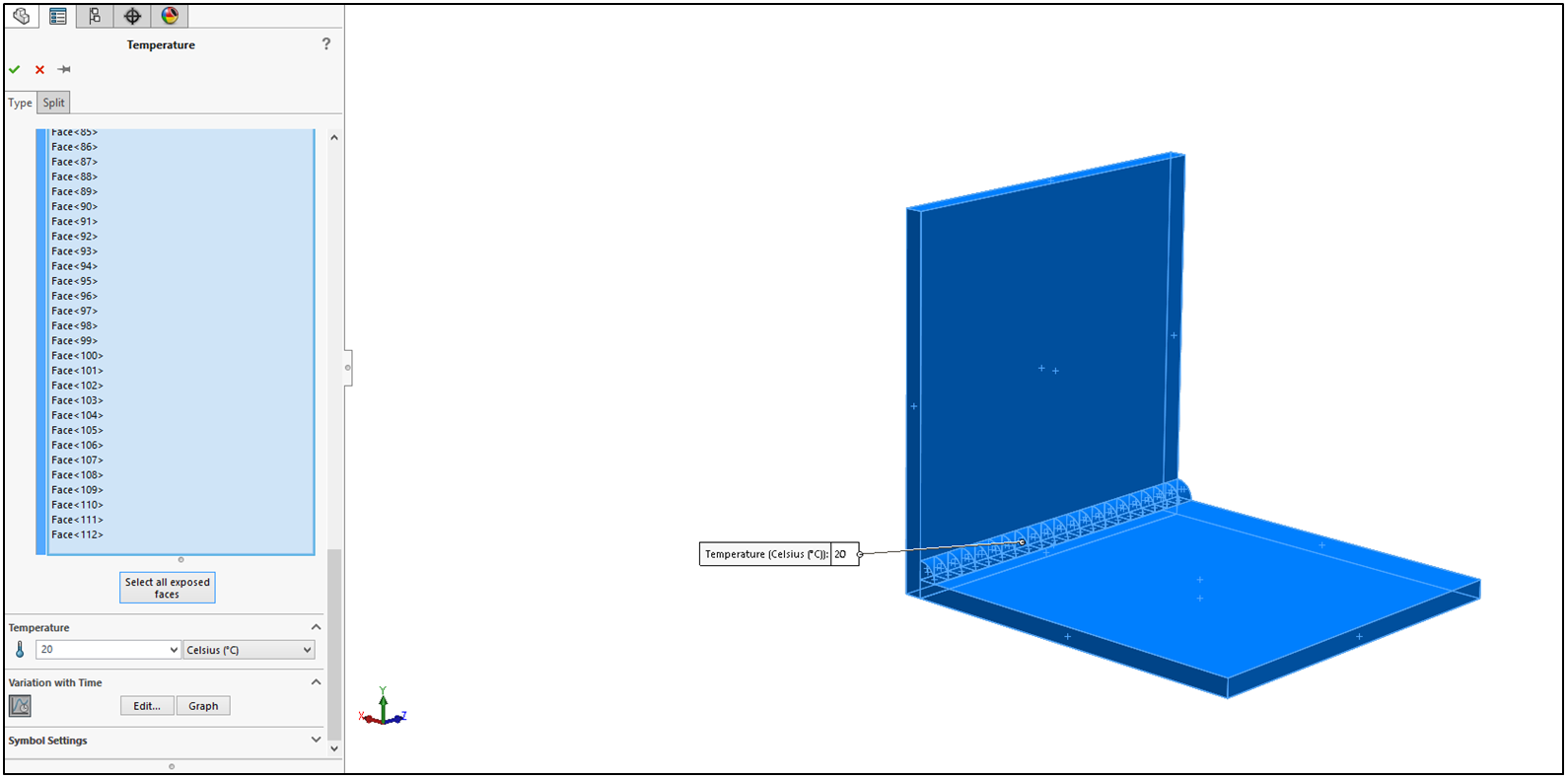 pic.5 Initial temperature definition
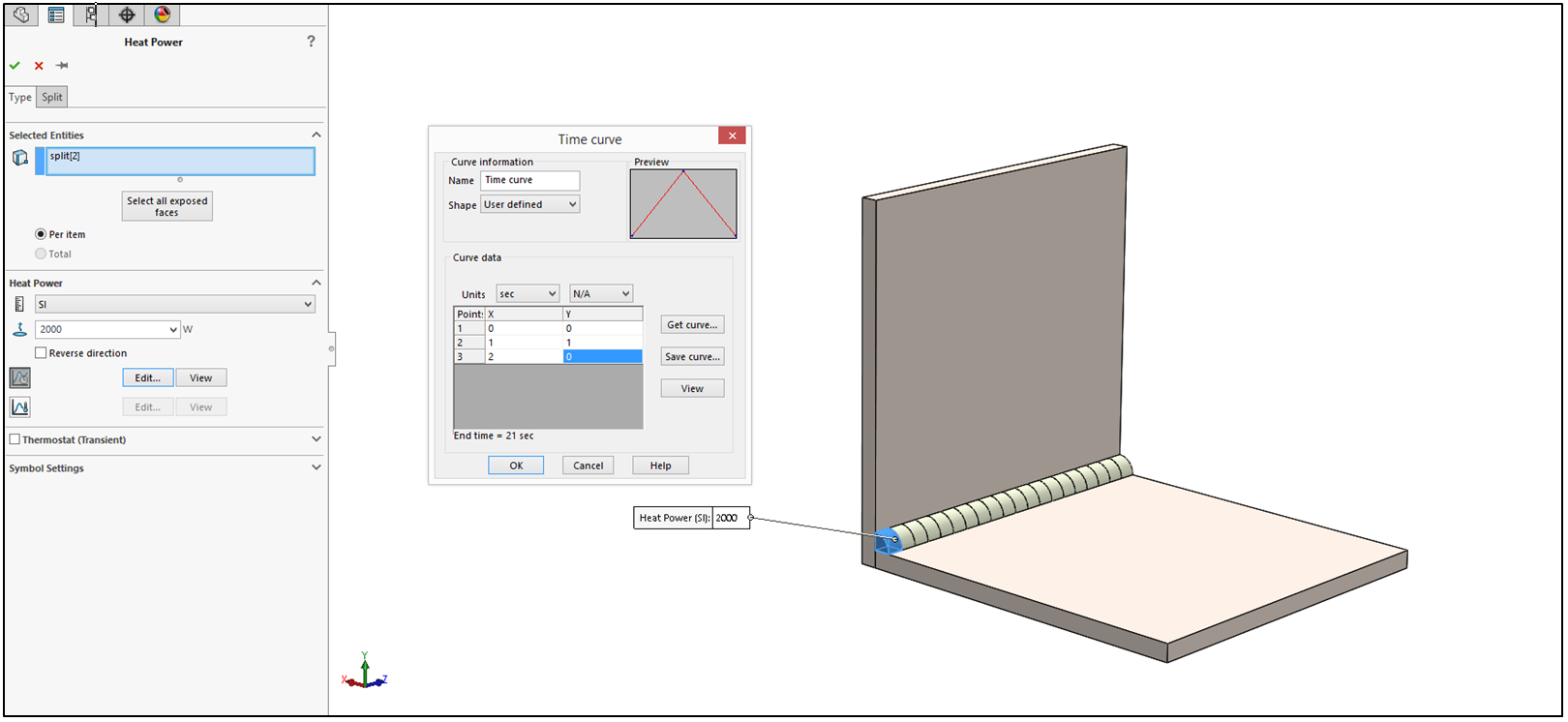 pic.6 Definition of thermal loads on the first piece of weld connection
 pic.7 Definition of thermal loads on the second piece of weld connection
Now we can run the study which results are presented below as animation.
In the last step we will create nonlinear study (available only for Premium Simulation). In the study, properties in Solution tab End of stepping time should be set to 21 seconds with fixed Time increment to 1 (pic. 8). In the Flow/Thermal Effects tab Temperatures from thermal study option should be picked up (pic. 9). We add global contact – bonded and define fixed geometry on the bottom surface of bottom plate and run the study.
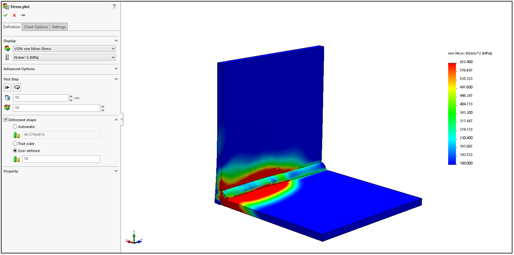
As a result we can analyze Stress distribution (pic. 10a) and Displacement plot (pic. 10b) for chosen second of the analysis or for all iterations at once (pic. 11a – stress, pic. 11b displacement). The results are also represented as animation below (stress and displacement respectively with the deformation scale of 10).
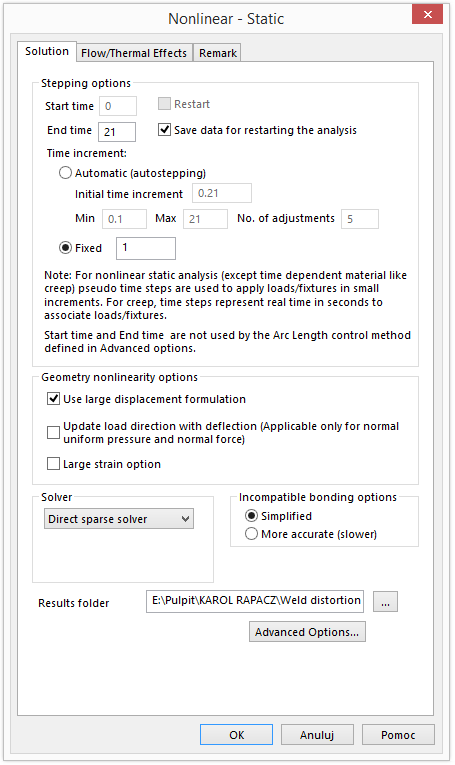
pic.8 Properties of Nonlinear study (Solution)

pic.9 Properties of Nonlinear study (Flow/Thermal Effects)
 pic.10a Stress plot in 10th second
 pic.10b Displacement plot (distortion) in 13th second
 pic.11a Stress plot for whole study
 pic.11b Displacement plot (distortion) for whole study
If you want to check up study definition on yourself you can download it from DROPBOX from link below
In the following article you will find out how to estimate weld distortion using SOLIDWORKS Simulation.
Our case study consists of two metal sheets which will be welded together – we want to find out what is the distortion and stress distribution resulting from the thermal load (pic. 1). The length of weld connection is 100 [mm] and the welding speed is 0.3 [m/min] that gives us 20 seconds of welding time.

pic. 1 Case study – Two metal sheets which will be welded together
The first thing we have to do is to model 3D geometry of weld connection (pic. 2). Then we should split our weld model into smaller pieces adequately to the welding time – 20 seconds = 20 pieces
(pic. 3).

pic.2 3D model of weld connection

pic.3 Weld connection after splitting
The next step is to define new thermal study. In the study properties we change Solution type to transient and the total study time to 21 seconds (pic. 4).
Now materials should be defined both for metal sheets and weld.
Two kind of thermal loads will be added to the study. Firstly, temperature load – we pick initial temperature and then select all exposed faces option and set the temperature to 20 [°C] (pic. 5).
The second thermal load will be Heat power with the value of 2000 [W]. In that case we will use time curve and set it as follows – for x=0 (second 0) y=0 (no thermal load) for x=1 (second 1) y=1 (thermal load 2000 [W]) for x=2 (second 2) y=0 (no thermal load). This operation should be repeated for all the pieces of weld with proper timing (pic. 6, pic. 7).
pic.4 Properties of Thermal study
pic.5 Initial temperature definitionpic.6 Definition of thermal loads on the first piece of weld connection pic.7 Definition of thermal loads on the second piece of weld connectionNow we can run the study which results are presented below as animation.
In the last step we will create nonlinear study (available only for Premium Simulation). In the study, properties in Solution tab End of stepping time should be set to 21 seconds with fixed Time increment to 1 (pic. 8). In the Flow/Thermal Effects tab Temperatures from thermal study option should be picked up (pic. 9). We add global contact – bonded and define fixed geometry on the bottom surface of bottom plate and run the study.
As a result we can analyze Stress distribution (pic. 10a) and Displacement plot (pic. 10b) for chosen second of the analysis or for all iterations at once (pic. 11a – stress, pic. 11b displacement). The results are also represented as animation below (stress and displacement respectively with the deformation scale of 10).
pic.8 Properties of Nonlinear study (Solution)
pic.9 Properties of Nonlinear study (Flow/Thermal Effects)
pic.10a Stress plot in 10th secondpic.10b Displacement plot (distortion) in 13th secondpic.11a Stress plot for whole studypic.11b Displacement plot (distortion) for whole studyIf you want to check up study definition on yourself you can download it from DROPBOX from link below
0 comments:
Post a Comment
Note: only a member of this blog may post a comment.